Saturday, December 17, 2022

Proto 2000 GP30 Drive Overhaul

In the spring of 2020 I purchased an undecorated Proto 2000 GP30 on eBay with the plan of eventually finishing it as TP&W #700. The seller's description noted that some paint had flaked off of the frame, which didn't seem like a big deal to me. I wasn't prepared for the mess that awaited me when I received the locomotive and took my first look inside the box. 


The paint was coming off of the frame in tiny flecks that coated the motor and drive train. It looked like someone had seasoned the mechanism with black pepper. I've never seen anything quite like this before and I don't know what would have caused it. It was a real mess, but I do enjoy cleaning and have been kind of looking forward to this project for a while because it will be very satisfying to get this unit cleaned up and operational. The tune-up turned into a rather involved project that took me several months to finally finish.

First, I completely disassembled the mechanism. A few more surprises awaited me.

There are four screws that attach the big weight to the frame. Two of them are at the ends and two of them are hidden by the fuel tank. I was not expecting the fuel tank to be attached with tape, and it was surprisingly difficult to remove.

I also wasn't expecting to find masking tape on the bottom of the motor. I guess this tape was intended to ensure that the bottom motor clip and/or orange wire wouldn't make contact with the frame.

I've read many horror stories of Proto 2000 truck gearboxes being filled with a grease that solidifies to a peanut butter-like consistency as it ages. I was pleasantly surprised to not find that stuff in my GP30.

It was altogether unsurprising to find that all 4 axle gears were split. This is perhaps the defining characteristic of Proto 2000 locomotives from the 1990s.

I discarded the axle gears and gave all of the remaining truck parts and universal couplings a bath in warm soapy water to wash off the oil and paint flakes. I gave the frame a bath of a different sort.

I soaked the frame in Super Clean degreaser for a couple of days to remove the rest of the flaking factory paint. A tennis ball can works great for this job. It has a tight-fitting lid, and it's almost the perfect size for 4-axle HO locomotives and 40-50' freight cars.

It would have been ironic if the Super Clean failed to remove the remaining paint from the frame, and indeed the frame didn't look much different after soaking for 24 hours. However, the surviving paint came right off with a little scrubbing with an old toothbrush under running water. I thoroughly rinsed the frame with water, let it air-dry, and repainted it with flat black spray paint from Ace Hardware.

I learned the hard way that it is essential to put insulating tape on the frame below the motor. I had completely reassembled the locomotive without this tape, and when I tested it on DCC it took off at a constant speed that I couldn't change with the throttle. Even though my ohmmeter showed no continuity between the bottom motor clip and the frame, adding polyimide tape between the motor and the frame solved the problem. Luckily the decoder was not damaged.

I opted to replace the Proto 2000 Blomberg sideframes with better-detailed Athearn parts. TP&W 700 rode on traded-in trucks from F3 #100. These trucks had a mixture of square and sloped bearing caps that differ from the roller bearings on the Athearn sideframes. The square and sloped bearings really stand out to me, especially because the trucks are painted silver, so I decided that it would be worth the effort to carve off the cast roller bearings and substitute aftermarket square and sloped bearing caps from Details West. 

I was hardly looking forward to carving off 8 cast-on roller bearings, but the job was less tedious that I expected. It wasn't practical to use a file to smooth the affected area, so I mostly scraped the area smooth with my knife.

After I finished carving off the cast bearings, I glued on the Details West parts with cyanoacrylate. Two of the prototype sideframes had 2 square bearings and the other 2 had 2 sloped bearings. The square bearings looked pretty good to me, but the sloped ones just didn't look right. The Details West parts seemed too bulky to me and not sloped enough, and they also have a bolted-on plate detail where the prototype is smooth. I looked into other options and found some Athearn Genesis parts. The photo above shows the Details West sloped bearing on the left and the Athearn sloped bearing on the right. The Athearn parts looked much better to me, so I carefully popped off the Details West parts with my knife, scraped off the dried glue, and glued on the Athearn parts.

When I went looking for alternatives to the Details West sloped bearing caps, I thought there was an Athearn option but I had trouble finding it. My searches for "Athearn sloped bearing" came up empty. Eventually I figured out why: "sloped" is misspelled as "slopped" on the package. Oops.

The locomotive made a squeaking noise when I test-ran it after installing the modified sideframes. The squeaking was caused by the wheels rubbing against the sideframes. I solved this problem by adding shims of 0.040" x 0.010" styrene to the backs of the sideframes.


I swapped out the 2,500 gallon fuel tank that came installed on the model with the 1,700 gallon tank from the parts bag. I didn't like the idea of securing the fuel tank with tape, so instead I used two 0-80 screws. It took me way too long to realize that the air reservoirs are supposed to snap over the sides of the frame. Until I figured that out, the fuel tank was a really loose fit.

The Proto 2000 GP30s came equipped with low-voltage headlight bulbs. I decided to replace these with white LEDs. I used NTE #30143 white LEDs that I bought at Micro Center. These LEDs come packaged with 220 ohm resistors, but these were too small for my application. The spec sheet for these LEDs list a forward voltage of 3.2 V and a maximum continuous forward current of 25 mA. On DCC, I measured a voltage of 13.6 V across the headlight pins. I calculated the minimum resistor needed using Ohm's Law as follows:

The closest available resistor at Micro Center was 470 ohms, and the next size up was 1,000 ohms. I bought and tested both. These LEDs are extremely bright and I didn't notice much difference in brightness when using the 470 ohm versus the 1000 ohm resistor. I ended up using the 1,000 ohm resistor to keep the current well below the LED maximum. 

The LEDs I used, and the assembly I made for the rear headlight. The resistor is on the cathode (negative lead, yellow wire) under the heat-shrink tubing. The resistor can go on either the anode or the cathode; most examples I found on the web show it on the cathode for some reason, so I did it that way too.

Converting this locomotive to DCC was a real headache, though I have to admit that I made it a lot more complicated than it really needed to be. TCS makes a decoder, the LL8, that is designed to be a drop-in replacement for the original circuit board in these locomotives. However, the LL8 is quite a bit more expensive than other TCS decoders that are more universal and have fewer functions. My cheap side won out and I opted to trade what I thought would be a little more work for a less expensive decoder.

The TCS website has a helpful library of decoder installations in a wide variety of locomotives. After looking at several different installations in similar Proto 2000 locomotives, I opted to try the DP2X. 

I reconnected the wires to the 8-pin socket so that it would face upward. I covered the frame below the plug with polyimide tape to prevent a short. I used one of the original circuit board mounting screws to hold the socket in place. 

The DP2X is a tiny circuit board that plugs right into the 8-pin socket.

Everything seemed good with the DP2X installation until I test-fit the body shell. The shell fit, but the DP2X was pressed up against it. When I test-ran the locomotive in this configuration, the shell did get warm from being in contact with the decoder. I doubt the decoder would have gotten hot enough to melt the plastic, but this still didn't seem like a good permanent setup. I installed the DP2X in my Atlas C424 (TP&W #801) instead and went back to the drawing board for the GP30. 

I ended up using a TCS T1 instead. I thought about hard-wiring the T1, but had I done so I wouldn't have been able to disassemble the locomotive again without unsoldering or cutting wires. I ended up keeping the Life-Like 8-pin socket and using a Digitrax short harness to connect the 9-pin plug on the T1 to the 8-pin socket.

Here's the locomotive along with the T1 decoder and the Digitrax harness. I had to rotate the 8-pin socket by 180 degrees from how I had it set up for the DP2X to get the pins in the correct orientation to use the harness.

Here's the final installation. The wires on the "short" harness were still a bit too long, so I had to gently put a Z-bend in them to get the decoder to sit where I wanted it. In this configuration the top of the 8-pin plug might touch the shell, but the decoder definitely won't.

The shell fit just fine on the reassembled drive with the T1 decoder. The truck sideframes look great, and I'm glad I took the time to modify the bearing caps.

And with that I finally have the GP30 drive ready to go. I'm going to take a break on this project for a while and paint the shell for TP&W 700 at a later date.

Saturday, November 5, 2022

DCC-EX

I've debated for a while whether I should convert my layout to DCC. My venerable MRC Tech 4 power pack has done the job up to this point, but some sort of walkaround control will be necessary once I finally do build my planned shelf extension to the current tabletop layout. I've been hesitant to make the switch to DCC primarily for 2 reasons: cost and increased complexity. I priced out the DCC starter systems from Digitrax, NCE, and MRC and concluded that it would cost $200-$300 just to get a walkaround DCC system, not including the cost of decoders. Being a somewhat miserly individual, it was difficult for me to justify spending this much money on a control system for my small, one-train layout. On the complexity front, I've been reading about DCC technical issues for years in hobby magazines and online forums. I deal with software gremlins enough at work, and the thought of introducing debugging into my hobby was not appealing. 

If I had been in this situation 20 years ago, I probably would have just purchased a DC walkaround throttle. Today, however, a DC walkaround throttle wasn't a great option. There are very few options for new ones, and I was surprised that even the prices for used ones on eBay weren't that much less than a starter DCC system with far more capabilities. Plenty of circuits for DC throttles have been published over the years, and while such a setup could be built for relatively low cost, I'm not well-versed in electronics and I knew it would take me a lot of time to pick a design, find and purchase the correct parts, and assemble it. It therefore seemed inevitable that I would eventually convert my layout to DCC, but I continued to be hung up on the cost. 

The game-changer came last year when I learned about DCC-EX (formerly DCC++EX), an open-source DCC project based around the Arduino microcontroller. DCC-EX is billed as a do-it-yourself DCC system for less than $100, which appealed to both the tinkerer and cheapskate in me. I acquired the necessary parts over the summer and built the system this fall. The combined cost of the system components was indeed less than $100, but there are a few caveats:

  1. DCC-EX requires a computer, and for convenience it kind of needs to be close to the layout. I was fortunate to already have a surplus laptop that could become my layout computer, but the system would cost more if you had to purchase a computer to use with it. 
  2. The only way to control trains in the most basic DCC-EX setup is to do so through the EX-WebThrottle on the computer. To get my desired walkaround control, I use the Engine Driver app on my smartphone. As with the computer, I already had a smartphone that would work but the system would cost more if you had to acquire a suitable wireless device for walkaround control.
  3. The system developers have volunteered substantial time and effort to write the code, test the system, and provide comprehensive instructions. The code may be a free download, but I also made a donation to support the project.


From left to right, the Arduino Mega, the Arduino Motor Shield, and the MakerFabs WiFi board. The Mega is the brains of the system, the Motor Shield provides the power to the track, and the wifi board allows me to use a smartphone as a throttle. I purchased both Arduino boards from Amazon. I had to order the wifi board directly from MakerFabs in Hong Kong, and it took a while to arrive.

Assembly is pretty simple; just stack the boards and run two jumper wires from the Mega to the wifi board. The Motor Shield only has screw terminals for power inputs, so the thing sticking out to the left is a barrel plug adaptor for connecting the power supply.

I used an adjustable "wall wart" power supply for the Motor Shield. As shown, I set the output voltage to 15V. I used a separate 9V wall wart (not shown) to power the Mega.

I rearranged the shelves underneath my layout to make room for the computer, and I mounted the DCC-EX system nearby on the layout frame. I used some old Code 100 sectional track from a previous layout to make a programming track on the shelf.

My TP&W GP35 was the first locomotive in my fleet to get a decoder. Because it has a 9-pin plug, I used the TCS T1A. It was a very simple, plug-and-play installation.

I thought the instructions on the DCC-EX website were very good. I had no issues assembling the components, loading the code, and running my GP35 with the computer-based throttle. The only thing in this process that wasn't super clear to me was when to connect the Mega and Motor Shield to their power supplies. I probably connected the Mega power supply sooner than I was supposed to, but that didn't seem to cause a problem. I think you're supposed to wait until after the code is loaded onto the Mega to connect the power supplies.

The only place where I had trouble was getting the Engine Driver app on my phone to connect to the DCC-EX system. With my phone connected to the DCC-EX Wifi network instead of my home wifi network, the instructions made it sound like Engine Driver would automatically discover the DCC-EX network but for some reason this was not the case for me. I had to manually enter the IP address and port number, and I had a hard time figuring out what the port number should be. There is some conflicting information in the videos on the DCC-EX website, but eventually I figured out that the correct port number is 2560, as shown on the screen shot below. 


I've been using DCC-EX for about a month now, and so far I like it. Having wireless control has been great, and though I'm still adjusting to the slider bar on my phone, I don't really miss having a knob for speed control. I haven't done any programming beyond changing the address, but at some point in the near future I will probably mess around with the speed tables and momentum. This might sound a little silly, but what I probably like the most about DCC so far is bright headlights. I've been so used to dim or dark headlights when running at very slow speeds on DC that it's a very noticeable and welcome change to now have the headlights be at full brightness all the time. 

I'm almost done with my second decoder installation, and that will be part of my next post.


Monday, August 1, 2022

Let There Be Streets

Over the last few months I've added some streets and grade crossings to the layout. I wanted to have streets in place prior to making scenic contours and build the grade crossings prior to ballasting the track so I wouldn't have to excavate ballast away from the crossing locations.


Streets

For the streets themselves, I used 8-mm EVA foam purchased from Michael's. I've seen others make very convincing streets with EVA foam, and I had no interest in using plaster for streets again like I did on my first layout. I chose the 8 mm thickness so I wouldn't have to use multiple layers to get the road surface at an elevation slightly below the tops of the rails. 

The foam cuts nicely with a sharp X-acto knife, but I found I needed to change blades frequently to avoid getting a rough, tattered edge when the blade began to dull. I cut scale 24-foot-wide strips of foam from the roll and then trimmed them to fit on the layout. 

I used yellow carpenter's glue to attach the foam to the plywood tabletop. A plastic knife was handy to spread a thin layer of glue on the bottom of each piece of foam.  

The foam retained quite a bit of curvature from being rolled up. Real streets are a bit higher in the middle to promote drainage, but not quite to this level.

Quite a bit of weight was necessary to keep the foam flat while the glue dried. The wood spacer is there for more even weight distribution to avoid making impressions in the foam. The brown "distilled water" is water that I've used to clean paintbrushes, by the way. 

Success. A nice flat street.

I plan to paint the foam streets at a later date once I have the surrounding scenery in place.

The "Hill"

I get a little defensive when people deride Illinois (and other Midwestern states) as "flat and boring." Florida is extremely flat, and yet I never hear the same criticism leveled (pun intended) at the Sunshine State. While my native Peoria region has plenty of topographic relief, I do have to grudgingly admit that the area in and around El Paso that I'm modeling is indeed pretty flat. However, there are subtle differences in elevation that I hope to capture on the layout. The east-west downtown strip along Front Street that faces the TP&W is several feet above the track level, and the north-south streets dip down where they cross the tracks. I decided to add a small "hill" to the north-south street (Elm Street) that runs down the middle of the layout. I used two different sizes of wood shims to make the slopes with a piece of moulding between them to flatten out the crest. My Surform plane worked well to shape the moulding and I used a 60-grit sanding block to smooth out the transitions.


Paved Crossings

As best as I can tell from photos, most of the grade crossings in El Paso were of the type with a single railroad tie on either side of each rail and asphalt pavement up to and in between the ties. I built two curved crossings like this using styrene strips for the ties and lightweight spackling compound to fill the space between the rails. 

Both styrene "ties" have an L-shaped cross section. The outside ties were made by laminating 0.030" x 0.100" and 0.040" x 0.060" styrene strips to form an inverted L to clear the molded spike heads. The inner ties were made by laminating 0.040" x 0.080" and 0.020" x 0.100" styrene strips into an L for wider flangeways. I glued my faux ties to the actual ties using cyanoacrylate gel. The molded spike heads served as guides. 

I removed the cork roadbed within the street footprint so I could butt the foam right up against the track. I made a paper template for cutting the foam to the correct shape.

To clear the actual ties and roadbed, I had to make a notch in the underside of the foam. I first sliced the end of the foam parallel to the road surface, then made several light vertical passes on the bottom of the foam until I had connected the two cuts. A sharp, new knife blade was essential.

The plastic knife also made a good applicator for the spackling compound that I used to fill in the middle. A moistened scrap of foam worked well to smooth the spackle between the styrene "ties". The additional water caused the spackle to shrink a bit as it dried, so I came back later and applied a thin final coat. I lightly wet-sanded the finished surface with 320-grit sandpaper to both smooth the surface and remove the thin coating of spackle on the inner "ties."
 

I primed the "ties" on the first crossing I built with Vallejo gray primer prior to installation and figured I'd paint them later, but for the second crossing I spray-painted the "ties" with Rustoleum Camouflage Brown before I glued them down.  

Wood Crossings

For the two crossings on Elm Street, I used laser-cut wood crossings from Blair Line. These come in straight versions as well as curved versions in a number of different radii, and I thought they would be a simple, drop-in installation. Unfortunately, the wood crossings turned out to be the more difficult of the two types of crossings I made for the following reasons:

  1. They're too thick for Code 83 track. The Blair Line wood pieces are 5/64" (0.078") to 3/32"(0.094") thick, in other words approximately equal to slightly greater than the 0.083" rail height. I built styrene jigs to hold the wood pieces in place and guide the final thickness as I sanded their bottom sides with 60-grit sandpaper. I thinned the pieces that go between the rails to approximately 0.060" thick. The outside pieces need to have an inverted "L" profile to clear the molded spike heads, so I thinned them to 0.030" and glued them to thin strips of 1/32" basswood.
  2. The curved crossing is too short for a 2-lane street. The Blair Line 21-23" radius curved crossing is about the same width as the straight crossing, but a curved track takes a longer path through the street and therefore needs to be longer than a straight crossing. Luckily the Blair Line crossings come in packages of 2 so I had additional material available to lengthen my curved crossing, but of course now I don't have enough material left over for a second crossing.

My modified Blair Line crossings. The stock curved crossing has 4 sections but is too short, so I cut the 5th section to make it long enough to span the scale 24-foot-wide street. The outer pieces of the curved crossing at left are upside-down to show how I made them L-shaped to clear the molded spike heads.

I used an ebony Minwax stain marker to stain the wood crossings. 

The finished wood crossings. 


Saturday, April 30, 2022

Switch Stands

Before ballasting the track I needed to finish a few things related to my turnout controls. This post will describe how I:

  • Added TP&W-style targets on 2 Caboose Industries #204S high-level switch stands
  • Installed a Proto:87 Stores operating switch stand target on a remote-controlled turnout.

Targets

The TP&W's switch stands had high-level targets consisting of a green circle and a red arrow. When the switch was lined for the main, the crew of the approaching train would see the green circle. When the switch was thrown, the target would rotate 90 degrees so that the crew would see the red arrow pointing in the direction of the diverging route. Many of these switch stands are still in use on today's TP&W. 

Switch stand on the TP&W at Weston, Illinois, lined for the main. 2019 image from Google Street View.

I'm not aware of any commercially-available parts for this target style, so I had to make my own. I ended up making arrows from 0.010" styrene and splicing them together with circular targets from Central Valley's #1604 switch stand kit. 

With the circular target still on the sprue, I used a razor saw to cut a radial slot in the target. The raised lines on one side of the target worked well as a guide for the saw blade.

The diameter of the circle (7/32") defined the height of the arrow. I eyeballed the rest of the arrow dimensions from prototype photos.

I used a knife to cut a slot in the arrow.

I carefully slid the arrow into the circle and used a bit of liquid plastic cement (Micro Weld) to bond them together.

Mounting on Caboose Industries Switch Stands

Two of my manually-controlled turnouts are equipped with Caboose Industries #204S sprung switch stands. I installed these back in 2019 when I laid the track and they've worked great so far. Now I'm finally getting around to finishing them with targets.

I used cyanoacrylate (Loctite gel) to attach the target to the vertical wire on the switch stand. Again eyeballing off of prototype photos, I left a gap approximately equal to the target height between the top of the stand and the target. I used wire cutters to trim the excess wire above the target.

I removed the target/wire/gear assembly, painted it at the workbench, and then reinstalled it. The red is Vallejo Model Air 71.003 Red and the green is Vallejo Game Air 72.732 Escorpena Green.

Here's the other Caboose Industries switch stand. Lined for the main...

...and lined for the diverging route.


Proto:87 Stores Operating Target

There is a turnout in the center of the layout that is remotely controlled with a Tortoise switch machine. At the time I laid the track, I figured I would just mount a non-operating Central Valley switch stand next to it. Thinking ahead to how I might operate the layout in the future, I like the idea of installing a second toggle switch for the Tortoise so I can throw it from either side of the layout. In this configuration, the toggle switch position doesn't necessarily indicate the turnout position, so an operating switch stand would be useful.

After doing a little research, I decided to try the working switch stand indicator made by Proto:87 stores because it seemed like the best option for an already-installed turnout. Central Valley and Rix also make operating switch stands. I couldn't find instructions for the Central Valley product, but from looking at pictures of the parts it seemed like it is designed to be used with Central Valley's turnout kits and wouldn't be easy to retrofit onto an already-laid Atlas turnout. The Rix switch stand is a low-level design that doesn't match the TP&W prototype. 

Installing this switch stand mechanism just might be the most frustrating thing I've done so far this year. There were several moments when I almost gave up on it, but after changing my approach multiple times I ultimately saw it through to completion. The Proto:87 kit consists of a fret of etched stainless steel parts, a Central Valley switch stand, a stiff piece of wire with a sharpened end for the vertical post, and a springy piece of wire to connect to the turnout throwbar.

The heart of the Proto:87 kit is this gearbox. (The picture shows the parts for two kits.) The gearbox gets mounted underneath the switch stand. The disc gets sandwiched inside the folded flat plate and rotates a wire mounted vertically through its center. A second wire connects the turnout throwbar to one of the outer holes on the disc, and one of the crescent-shaped slots on the gearbox limits the rotation to 90 degrees. 

The kit does not come with instructions but they are available on the Proto:87 website. The instructions tell you to install the gearbox between the base of the headblock ties and the roadbed with its long axis parallel to the headblock ties. The actuating wire then connects the throwbar to one of the disc holes within the smaller of the two crescent-shaped slots in the gearbox. I simply could not get the installation to work in this configuration. The smaller crescent-shaped slot did not allow the Tortoise to move the switch points all the way to the diverging route, even with a Z-bend in the actuating wire as recommended in the instructions. With the gearbox in contact with the cork roadbed, I also worried that it would be too easy to get ballast adhesive in the gearbox and gum up the works.

The instructions don't say anything about the larger of the two crescent-shaped slots, but I figured that it must be intended for turnouts with longer throw distances, like my Atlas Snap-Switch. In order to use the larger slot, the gearbox must be rotated 90 degrees from the configuration shown in the instructions. I ended up building a gearbox mount out of styrene that would securely hold the gearbox in this configuration and raise it above the roadbed to keep it away from ballast glue.

The gearbox mount under construction. The bottom and middle layers are in place.

The mount was made from 3 layers of styrene and has a total thickness of 0.080" to match the Atlas ties. The middle layer is 0.020" thick to match the gearbox thickness, and the gearbox gets sandwiched between the top and middle layers.
  • Bottom layer - 0.030" styrene sheet
  • Middle layer - 0.020" x 0.100" and 0.020" x 0.040" styrene strip
  • Top layer - 0.030" x 0.100" styrene strip
Once the second layer was in place to define the total size of the mount, I trimmed away the bottom layer around the perimeter, between the headblock ties, and under the center of the gearbox. I drilled four #61 holes (one at each end of the headblock ties) so I could use Atlas track nails to secure the mount to the layout. I painted the ties with Vallejo Game Air #72-745 Charred Brown and used a black Sharpie to color the white styrene where it would show through the holes in the gearbox.


My homemade gearbox mount, gearbox, switch stand, and wire for vertical post. I left the location of the switch stand unpainted for now. 

At this stage, I slid the gearbox into its slot and temporarily mounted the assembly on the layout so I could configure the actuating wire. Much of my frustration with this project resulted from making adjustments to the actuating wire. I found this wire very difficult to manipulate with tweezers and needle-nose pliers because of its small diameter, and I also broke a couple pieces from too much bending. Once I thought I had the actuating wire cut to the proper length and bent into the correct shape, I installed the vertical post (a friction-fit into the center of the disc) with a temporary paper target cut from an adhesive label to test the operation.


Once the unit was operational, I shortened the actuating wire where it sticks up through the disc, removed the temporary target, and glued the switch stand to the mount. To provide enough clearance for the top of the actuating wire to clear the bottom of the switch stand, I used two bits of 0.040" x 0.080" styrene strip to shim up the switch stand.

Next, I made a target using the same method described earlier in this post and glued it to the vertical wire.

I moved the assembly back to the workbench for final assembly and painting. The vertical wire protrudes below the base of the gearbox, hence the 0.25" x 0.25" styrene blocks.

After all that, here's the final installation. The Proto:87 gearbox is a well-made product but it takes a lot of patience to configure it with a working switch stand.


Sunday, February 13, 2022

TP&W Boxcar 70001

A couple of years ago I found the Herald King B-433 decal set for a TP&W 50' modern box car in the bargain bin at my local hobby shop. For $1, I went ahead and bought it even though I had no plans at the time to build one of these cars.


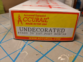
I later acquired an undecorated Accurail 50' exterior-post boxcar to use with these decals.


The First Attempt

I actually started this project a year ago thinking it would be a good practice airbrushing project. My original plan was to use Badger's MODELflex paints. Prior to getting an airbrush I had never considered using MODELflex because I remembered the Model Railroader product review from years ago that said it was a poor brush paint. I confirmed this when I tried to compare different options for TP&W red-orange on a piece of white styrene. I brushed small areas of the different MODELflex colors onto the styrene and was very disappointed in how the paint beaded up and wouldn't spread out to cover the surface or stay where I brushed it. 

I tried airbrushing the boxcar with 16-02 Reefer White and it didn't go well. The paint didn't atomize well and I ended up putting it on pretty thick to get an opaque coat. I didn't thin the paint (hey, it's advertised as airbrush-ready straight from the bottle!) and sprayed at 25 psi. If I were trying this today I would at least increase the pressure to get a finer spray and maybe thin the paint as well. While my issues spraying MODELflex were probably the result of my inexperience at airbrushing and not the paint itself, I gave up on MODELflex after this experiment because the poor brushing performance was a deal-breaker for me. It's pretty important to me to be able to do touch-up with a brush.

I tried removing the white MODELflex from the boxcar with 91% isopropyl alcohol and, even after a week of soaking in the alcohol, the paint wouldn't come off. This was surprising to me because up to this point I had always had very good luck with 91% alcohol. I also tried Windex, thinking that the ammonia in the Windex would attack the acrylic resin, but this was only slightly more effective than the alcohol. Ultimately I was successful in removing the MODELflex with Super Clean Tough Task Cleaner-Degreaser. This stuff contains sodium hydroxide, so I wore the thick, reusable rubber gloves when using it. After this experience, I have to say I was impressed with MODELflex's durability.

The Second Attempt

I came back to this project right after New Year's. I primed the car body and doors with Vallejo 70.601 Grey Surface Primer, and then sprayed the roof with Model Air 71.062 Aluminum. 

One goal of this project was to see how well I like Model Air 71.086 Light Red as TP&W red-orange. I'm aware that the real TP&W paint was officially orange (Sherwin-Williams "International Distress Orange" according to a former TP&W dispatcher), but to my eye it looks red in most all of the pictures I've seen. I really liked the Scalecoat II CN Orange-Red color that I used a couple of years ago on a 40' boxcar and caboose 529, and the Model Air Light Red appears to be the closest Vallejo match straight from the bottle to the Scalecoat color. It would certainly be easier for me to use a stock color rather than have to custom-mix one.

The Vallejo Light Red went on VERY light in the first coat, even to the point of looking yellow. It took several coats, even over the grey primer, to get the expected color. I mixed the paint 2:1 with gloss medium to get a decal-ready finish without a separate overcoat. The paint dries a little darker than it looks when wet, but the painted car looked quite orange to me. On the redder end of orange, but still definitely orange.


The Herald King decals, despite their age, went on nicely. Applying the "TP&W" speed lettering over the ribs went better than I feared it would, but I still had to come back at the end and do some touch-up with white paint where the decals cracked. I mostly used Microscale Micro-Sol to set the decals, but on one side of the car I had to use the stronger Walthers Solvaset to get the "TP&W" lettering to settle down over the ribs.

Before touch-up

After touch-up and clear coat

After wiping off excess decal solvent and lint from the car sides, I gave the entire car a couple coats of 26.518 Matte Acrylic Varnish, thinned 3:1 with Vallejo airbrush thinner. Here's the completed car:


I was a little surprised at how the doors ended up a lighter shade of orange than the rest of the car. The doors are cast in white plastic and the body was cast in dark red, but I primed all parts with the same grey primer.

For comparison, I coupled this car between my factory-painted Atlas C424 and the 40' boxcar I painted a few years ago with the Scalecoat II CN Orange-Red.


The freshly-painted Accurail car looks redder in the pictures than it does in person but, except for those doors, compares favorably with my other red-orange TP&W equipment. The Atlas C424 is more orange and the custom 40' boxcar is more red. I think the Vallejo Light Red on the Accurail car looks better with the lettering in place than it did right after I painted it, but I haven't come to a final decision on whether I will paint future cars and locomotives with stock Light Red or if I'll make a redder custom mix.

Now that this boxcar is out of the queue, I'll probably take a break from car and locomotive projects and focus on making some progress on the layout.

Sunday, January 2, 2022

Atlas C424 Maintenance

I started the new year with some locomotive maintenance. Both of my primary locomotives - C424 #801 and GP35 #902 - are having some issues. I decided to start with the 801, which needs attention for the following 2 reasons:

  1. It growls when running forward, though it's silent when running in reverse.
  2. It stutters in a few places on the layout, especially at the curved turnout.
The growl has bothered me for a while but I've just lived with it, mostly due to fear of damaging the shell while trying to remove it. However, the stuttering is completely unacceptable so it was time to face my fears and take the 801 into the shop for an overhaul.

Removing Atlas shells is a touchy process for me because I'm terrified of breaking off one or more of the latching tabs near the four corners of the shell. Once broken off there's really no way to fix them. To remove the shell, I inverted the locomotive on the workbench and one at a time gently pried each tab away from the frame with a small screwdriver and inserted a strip of index card between the tab and the frame. Once I had done this for all four tabs, I set the locomotive right side up and carefully lifted off the shell. 

One thing I noticed right away after removing the shell was that the motor was loose. I fixed this by tightening the two motor mount screws. You have to first remove the plastic fuel tank to access these screws.


The stuttering is almost certainly a power pickup issue. The locomotive nearly stalls when the rear truck is sitting on the frog of the curved turnout, so it would seem that the front truck must not be picking up power. I confirmed this by test-running the locomotive with only the front truck wires connected to the circuit board; it basically didn't run at all in this configuration.

I removed and disassembled the front truck. Here are all the parts:


The brass contact strips that rub the axle ends were oxidized and the axle bearings were flush with dirty grease.


I gave all of the truck parts a bath in warm, soapy water, scrubbing them with an old toothbrush. After letting the parts air-dry overnight, I started reassembly. I polished the contact points on the brass strips with a wire brush in my Dremel. To polish the insides of the axle bearings, I used a strip of 600-grit sandpaper wrapped around a piece of styrene rod and attached with double-sided tape. I also soldered the wires directly to the tabs on the brass strips and omitted the plastic clips. The wheels weren't too dirty, but I polished the treads with the Dremel wire brush anyway.


Next I reassembled the gearboxes. Two of the three spur gears are identical and the third is slightly larger. The exploded parts diagram was not helpful for reminding me which gear went where; I found out through trial-and-error that the larger one goes in the position farthest from the worm gear. I lubricated the axle bearings with Labelle 108 oil prior to reinstalling the sideframes. I also lubricated the worm bearings with Labelle 108 and used Labelle 102 on the gears.

After completing the reassembly and reinstallation of the front truck, I test-ran the locomotive again with only the front truck wires connected to the circuit board. It ran much better than before, but this exercise illustrated just how important all-wheel electrical pickup is for good performance. While I had everything opened up, I removed the rear truck and gave it a similar bath and overhaul.

The fully reassembled locomotive runs smoothly and quietly through the curved turnout.


I suspect that the growling noise was related to the loose motor. As expected, cleaning all of the electrical contacts fixed the stuttering. Hopefully it will be a while before it needs the full overhaul again.